The M-04 MEMS INS product utilizes a MEMS inertial measurement unit (IMU) and an external (internal) GPS/BDS positioning module in a combined navigation system. HX Gyro inertial navigation system is capable of measuring the attitude, heading, speed, and position of the carrier, characterized by its compact size and high precision. The system internally integrates various sensors such as gyroscopes, accelerometers, magnetic compasses, temperature sensors, etc., and it employs a high-performance, small-sized microcontroller unit (MCU). It features adaptive wide-range power supply input and can interface with external auxiliary information such as an odometer.
Functions
- Autonomous Navigation Capability: It can provide reliable navigation data.
- Self-inspection Capability: It regularly checks the internal operation of the inertial navigation system and reports the self-inspection results and navigation status through the output protocol.
Specifications
| Performance Indicator | Remarks | |
| Pitch Angle Measurement Range | -90° to +90° | |
| Roll Angle Measurement Range | -180° to +180° | |
| Heading Angle Measurement Range | 0 to 360° | |
| Horizontal Attitude Accuracy | <0.05° (RMS) | |
| Heading Angle Accuracy | <0.8° | |
| Operating Temperature | -40°C to +70°C | |
The input/output connector model for the MEMS combined inertial navigation system is the shielded J30J-15ZKP.
| Pin | Name | Name | Pin | Name | Name |
| 1 | VCC | Power supply (9-28V) | 9 | GND | Communication ground |
| 2 | VCC | Power supply (9-28V) | 10 | GND | Communication ground |
| 3 | GND | Power supply ground | 11 | GND | Communication ground |
| 4 | GND | Power supply ground | 12 | RX1+ | RS4221 reception+ |
| 5 | RX2+ | RS4222 reception+ | 13 | RX1- | RS4221 reception – |
| 6 | RX2- | RS4222 reception- | 14 | TX1+ | RS4221 sending + |
| 7 | TX2+ | RS4222 sending + | 15 | TX1- | RS4221 sending – |
| 8 | TX2- | RS4222 sending – |
The interface for the MEMS combined inertial navigation system is RS422, with a baud rate of 921600bps.
Data format: 1 start bit, 8 data bits, no parity bit, 1 stop bit.
Data transmission period is 5ms, transmission method is blind transmission.
Bytes are transmitted with the high byte followed by the low byte, negative numbers are represented in two’s complement.
The product is multiplied by a scale factor when sent.
Applications
- Autonomous navigation and positioning of aircraft and helicopters
- Ship navigation and heading maintenance
- Attitude Control of Missiles and Unmanned Combat Systems
- Geological exploration and mining construction positioning
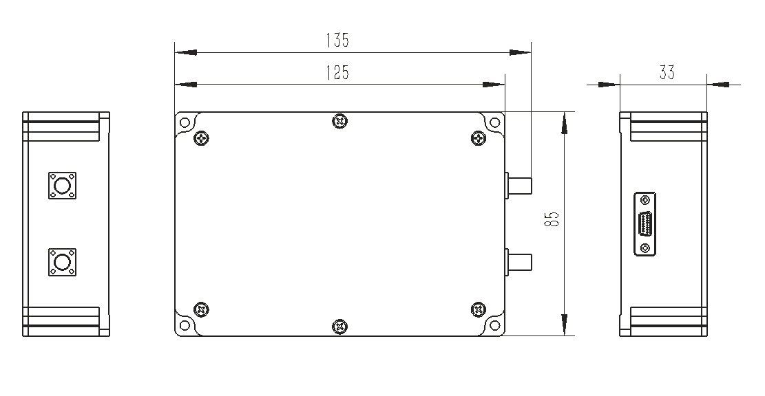
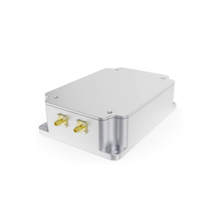
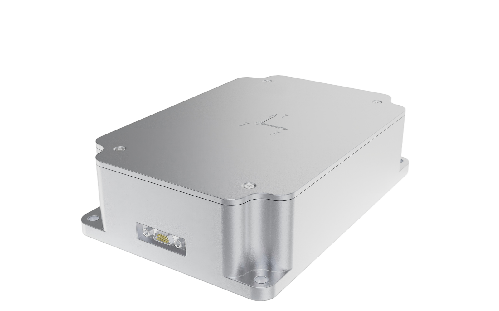
Diagram