The fiber optical strapdown inertial navigation system adopts a modular design, which is quick and easy to operate, with a simple and user-friendly software interface. This INSapplies multi-source information fusion processing technology, capable of collecting and processing various external input parameters such as odometer and Beidou satellite, receiving external control instructions, and completing initial alignment and navigation calculation. It provides real-time navigation information such as carrier heading, attitude, speed, and position. It can be used in fields such as vehicle and ship positioning and orientation, underground intelligent mining, track inspection, and surveying and mapping.
Functions
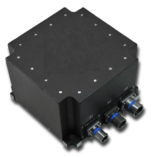
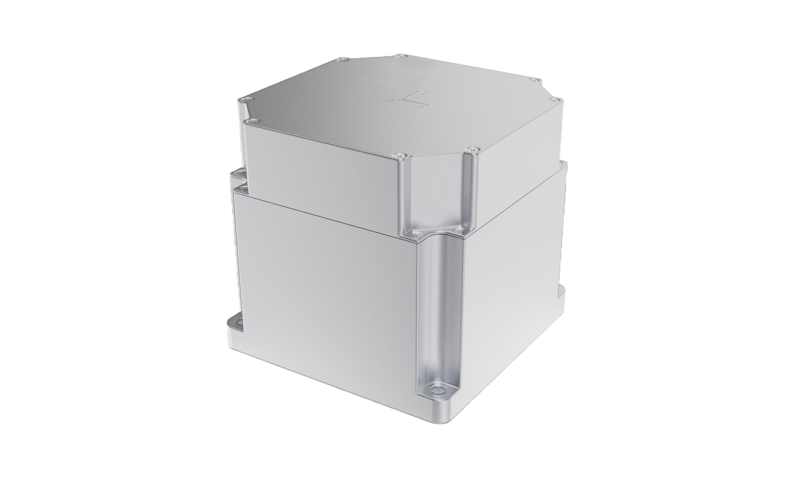
The main function of the F-05 Fiber Optical Inertial Navigation System is to provide an installation reference for the platform assembly internally and to provide a directional reference surface and installation reference surface externally, as well as to provide physical support for the electronic circuit board module, power supply module, and other components in the device.
The chassis adopts an integrated design, effectively improving the overall structural rigidity while meeting the requirements for weight, volume, vibration, and impact, and also taking into account the requirements for environmental adaptability.
Technical Features
North-Seeking Accuracy
The north-seeking accuracy of the equipment depends on the gyro bias stability. The system has performed temperature compensation on the gyro and taken gyro shielding measures, making the gyro bias stability less than 0.03°/h, which is equivalent to the east gyro bias stability being less than 0.03°/h.
The system optimizes the filtering algorithm during the north-seeking process and reduces the gyro’s random drift coefficient to control the alignment time within 5 minutes, with north-seeking accuracy better than 0.15°.
The specific implementation of static alignment is a solidified inertial system alignment of 0.5 minutes + Kalman filter alignment of 4.5 minutes, with a total alignment time of 5 minutes.
The system uses a high-precision Beidou receiver to achieve a horizontal position accuracy better than 3m.
Environmental Protection
Measures for environmental protection:
a) Sealing treatment of the chassis;
b) Surface coating: The printed circuit board surface coating with materials that are organically insulating and have good thermal conductivity;
c) Metal parts are made of materials with good corrosion resistance such as cadmium, nickel, or chromium plating;
d) Rational design to prevent electrochemical corrosion caused by contact between different metals;
e) The chassis base and inertial sensitive components separates physically, allowing for separate observation and repair or replacement;
f) Selecting waterproof components (such as waterproof switches, waterproof fuses, etc.) to replace the original components. And adding sealing gaskets to all external interfaces to improve the equipment’s water and gas tightness.
Shock and Vibration Resistance
The mechanical structure design adopts stress analysis, modal analysis, and other technologies to ensure that the equipment can adapt to shock and vibration environments from a design perspective. The internal connection wires of the equipment effectively fixwith wire clips to avoid unreliable connections due to suspension and swinging during shock and vibration. While the connection uses spring washers with tight screws or screw lock adhesive to ensure that the equipment can work reliably under working conditions with large shocks and vibrations.
Specifications
| Performance | Indicators |
| Azimuth Accuracy | Better than 0.15° (1σ) |
| Roll angle measurement accuracy | Better than ±0.06° (1σ) |
| Pitch angle measurement accuracy | Better than ±0.06° (1σ) |
| Horizontal positioning accuracy | Better than 3m |
| Operating temperature | -40℃ to +55℃ |
| Steady-state power supply input | 19V to 32V DC |
| Power consumption | ≤20W |
| Maximum external dimensions | 152mm (length) × 152mm (width) × 120mm (height) (tolerance ±2mm, excluding connectors) |
| Installation dimensions | 125mm × 125mm |
| Weight | ≤4kg |
| Interfaces |
1 power supply and 1 communication interface [DB-1 (debugging), DB-2 (IMU), and DB-3 (GNSS), all using serial communication protocols] |
Composition
The equipment functional modules include the chassis, platform assembly, electronic circuit board module, and power supply module.
The inertial components are installed on the platform to form the platform assembly, the platform assembly is installed in the chassis; the electronic circuit board module is placed on the side of the chassis; the power supply module is placed at the bottom of the chassis.
Diagram